
The Sailmaker provides information on the basics of fluid mechanics
The interaction of the forces generated by the wing effect describes the sailing behaviour. The keel and rudder are in the water, the sail in the air, the hull in both media. Differences and similarities of Sails, air and water form the basis.
The two decisive forces on the sail, buoyancy and resistance. We first look at the theory of potential flow on the sail in order to develop the essential basics for further understanding.
The boundary layer theory according to Prandtl solves an apparent paradox in the theory of smooth fluids. Sails and boundary layer theory. With the help of the rotational flow, it becomes clear why a tornado is white, among other things. Rotational currents on the sail.
We derive the lift force from the superposition of a parallel flow with a circulation flow around a circular cylinder. Together with the Bernoulli equation, the sail lift force is the difference in pressure between the top and bottom of the circular cylinder.
The Sailmaker informs about sails and wings in air and water
Sails in ideal fluid and two-dimensional flows
Sails in ideal fluid and two-dimensional sails, hull, keel and rudder are surrounded by fluid. To describe the buoyancy forces on the sail it is useful to make a few assumptions about the surrounding liquid. In the description of the sails, the following simplifying assumptions are therefore made in flow theory. The fluid is assumed to flow smoothly around the sail or wing. In theory, this means that no energy conversion from kinetic energy to thermal energy due to friction needs to be considered.
Furthermore, the simplification is that the nature of the liquid is homogeneous, i.e. it has the same properties in terms of toughness, density etc. at all points. Another assumption is that the liquid is incompressible. This means that it cannot simply be compressed, but only in accordance with an increase in pressure.
Segel und Potentialströmung
Potential flow around cylinder & wing profile
The forces acting on a sail or on a body in a liquid have their origin partly in its function as an obstacle, namely that the sail or body interferes with the free flow of the liquid, and partly in the flow conditions on the surface of the sail. In the case of the sail we have learned about both forces, the buoyancy at the sail and the resistance through the sail.
The flow conditions on the surface of the sail are caused by toughness effects. It is this frictional resistance that is necessary for lift to occur. But it is also what makes the mathematical models, which are simple in themselves, complicated.
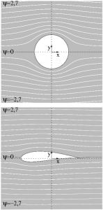
It is helpful for the understanding to look at simple streamlines around a circular cylinder. Using this model, the relationship between the shape of the sail or wing and the induced speeds, pressures and forces is explained.
Furthermore, we assume in the case of a potential flow that there is no separation of the flow from the wing. The fluid rejoins directly behind the wing. In reality, on the other hand, we often have to deal with flow separation. However, to describe the principle of lift, this phenomenon can be neglected.
Sails with lift and Bernoulli equation

Bernulli equation for flow
When a streamline image is viewed around a sail, the distance between the streamlines symbolizes the magnitude of the speed around the sail. The closer the streamlines come together, the greater the speed of flow at that point of the sail. The streamline diagram thus describes not only the direction of the flow but also the speed. It shows the speed field of the sail.
The velocity of a flow around a circular cylinder is equal to twice the initial velocity of the liquid multiplied by the sine of the angle formed by the point considered on the cylinder with the base of the circular cylinder.
The Bernoulli equation now establishes a relationship between the speed of the flow and the dynamic pressure of the flow, it says: The sum of static pressure and dynamic pressure is equal to the total pressure, and this is constant. The equation can be derived from the law of conservation of energy. The total energy remains constant, and in our case this is the pressure, static and kinetic.

Hydrodynamica Danielis Bernoulli
From the first formula, which describes the velocity, one can now calculate the pressure at any point in the liquid using the Bernoulli equation. The equation describes the mutual exchange between potential energy in the form of static pressure and kinetic energy in the form of dynamic pressure. Thus, if the speed of the fluid increases, and with it the kinetic energy, the potential energy in the form of static pressure decreases to the same extent.
One can compare the static pressure of compressed air with the potential energy of a tensioned spring. Another conclusion from the Bernoulli equation is that with increasing speed the pressure decreases. Emotionally, this does not seem logical, one rather associates high speed with high pressure. However, we must look at it differently: where the speed in a flow decreases, the kinetic energy is transferred into the form of static pressure, which increases at this point. That which is lost in one form of energy rises again in another form.
This means that in an ideal fluid, where no energy is converted into heat by friction, the energy conversion only results in changes in velocity and pressure.
In a real flow, in which a part of the kinetic energy is converted into heat by friction, the total pressure is no longer constant. If, however, the flow is rather slow, as in the situation of a sailboat, and the fluids have a very low viscosity, such as water and air, the Bernoulli equation provides very good approximations, since the proportion of energy converted into heat energy by friction is very small.
Sails and boundary layer theory by Prandtl
This is known as detachment of the flow, which results in a turbulent eddy area downstream.
Sails and rotational flow
Flows of this kind are also called vortex flows, and the cylinder is the vortex core. Such currents can be observed in nature in water and in the air.
From Bernoulli’s equation, according to which the pressure is low where the velocity is high, it can be concluded that the pressure in such a vortex flow is particularly low in the centre, because the velocity is highest there.
Sails and the principle of buoyancy
To obtain the resulting flow pattern, the velocity field, the two local velocity vectors, of the parallel and that of the circulation flow, must be added. The problem is thus solved in the same way as the determination of a resulting force as a vectorial addition of the individual components.
From the Bernoulli equation it follows that the pressure is greater on the upper side than on the lower side. Consequently, the difference in pressure results in a resulting force, which is called lift. This force moves the cylinder upwards, at right angles to the flow. A superposition of parallel flow with circulation flow thus causes a lift. A pure parallel flow around a cylinder, however, does not, the forces remain in balance.
It can also be shown that the magnitude of the resulting force, i.e. the lift, depends proportionally on the speed of the parallel flow (strictly speaking, it is the dynamic pressure resulting from the parallel flow), the circulation speed and the radius of the cylinder. The proportionality factor, also known as the lift coefficient, is the quotient of the speed of rotation and the speed of the parallel flow.